All Posts (14049)

Sort by

Long-duration HAB flight in progress

CNSPb.jpg?width=480The California Near Space Project is at it again.  Last year, they became the first team to achieve a transatlantic crossing using a latex weather balloon, and they launched from California.  Above is last year's flight path.

They have another long-duration flight over the great lakes right now, and you can follow the action here: http://aprs.fi/k6rpt-12.  Note that they're having some GPS trouble, so the position reports can be a little bit weird, but generally the position updates every 2 minutes.  More information on the team can be found on their website at http://www.californianearspaceproject.com

Read more…

Just sharing that the Aeromapper UAV is now ready to order with the new parachute recovery system.

Will very briefly describe a typical mission sequence so the basic setup of parachute + APM2.5 is explained (at the end). We think simplicity is king:

1. Assuming flight mission has been created on Mission Planner before, the UAV is launched manually and it will perform an automatic takeoff / climb to waypoint 1.

2. When hitting waypoint 1 the "photo sequence" starts by manually flipping the GEAR switch on the remote control (a Spektrum DX8). At that moment the camera lens cover on the bottom of the UAV opens automatically and the camera starts triggering every 3 seconds (triggering frequency is customizable every X seconds).

3. The UAV automatically flies to waypoint 2, then 3, a so on...  UAV can be returned to launch at any moment by switching to RTL or by turning off the remote in which case the failsafe will be activated (but the parachute does not deploys on failsafe).

4.  When hitting last waypoint, UAV heads toward home and loiters at an altitude of about 80 m (preset on Mission Planner). So this is when the human pilot enters back into action: first has to pause/stop the triggering sequence by flipping back GEAR switch. Then the ventral lens cover door will close automatically, protecting the lens of the camera on landing. Then, at the discretion of the human pilot according to the topography, wind speed & direction of the UAV the parachute switch is activated and ... voila!  See it land nicely for the next flight. The parachute can be packed back in a couple minutes (we'll post videos on this soon).

Thanks!

More info on the Aeromapper UAV here.


Read more…
Developer


3689489678?profile=original

When the ublox 6 series modules were released, I noted that the 6T and 6P modules provided access to the raw carrier phase measurements, and I started thinking about how to use this capability.  My connections through my university research appointment weren't strong enough to get ublox to sample a dev kit to me (they generally don't sample them at all).  Jordi and Chris from 3DRobotics.com were kind enough to use their customer relationship with ublox to get a sample 6T module and provided it to me mounted on the standard DIYDrones ublox LEA-6 module.  So mine looks just like the one above, except it has a 6T module instead of a 6H.


My prime curiosity was how good the carrier phase measurements from this module were.  The datasheet indicates that carrier phase measurements are available, but gives no specs about their accuracy.  So I had no idea if they would be of value.  Well, with a module in hand, some measurements made, and post-processing completed, I can tell you that there is tremendous potential here, but a lot of work before this is something ready for everyday use.


OK, what is carrier phase and why do I care?

A carrier phase measurement is a measurement of the phase of the arriving carrier wave signal from the gps satellite.  Think of it this way - as the radio signal from the GPS satellite travels from the satellite to your receiver it completes some fractional number of cycles of oscillation.  That means that the distance from the satellite receiver to you is some fractional number of wavelengths - say 100 million and 1/2 wavelengths.  The carrier phase measurement gives you the fractional value of 1/2 wavelength, or 180 degrees of phase.  That in itself is almost useless.  Fortunately the gps module gives us something a little better than that.  What it reports is the phase change (or the number of wavelengths of distance change) between the satellite and the receiver from one measurement epoch to the next.  So what we really have is a measurement of the change in distance between the satellite and the receiver over a known period of time.  And so theoretically, given that we know something about the location and velocity of all the satellites we should be able to use this information to calculate the (3D) velocity of the receiver.  Just one more thought on this topic - we could do the same thing with pseudo-range or Doppler measurements, which the receiver also makes, but carrier phase measurements have the potential to be orders of magnitude more accurate.


Nice, but what about position?

Well, the technique that I will describe below has some applicability to making very accurate position measurements, but lets just say it is really hard and is the kind of thing that only happens (still a relatively small number of) military gps with very large price tags.  I'll say some more about this later.  For now, we will just be looking at making velocity measurements.


OK, but what will we do with a great velocity measurement?

Well, imagine how much better position hold could work in a copter if the autopilot knew its 3D velocity vector to an accuracy of 5 millimeters per second.  Yeah, time for a double-take.  I said millimeters per second.  My initial test yielded a velocity resolution of 1 millimeter per second and an accuracy of better than 5 millimeters per second at a 5 Hz update rate.


There are lots of other things we can do with a better velocity estimate, like better acceleration modelling in the AHRS system, etc.


Let's see the data.

OK.  I have run two tests so far.  The first turned out fantastic.  The second had some difficulties, but still shows immense promise.  Below is a plot of the velocity estimate error during the first test.  This represents a bit over 5 minutes of data with samples at 5 Hz.

3689489765?profile=original


OK - let me describe a few things in this plot.  First, note that there are 5 `spikes' where the error is above 0.1 m/s.  These are 5 samples where the receiver did not have carrier phase lock on at least 4 satellites, and you need 4 satellites to get a valid solution.  For individual samples like this you can generally re-use the last velocity estimate.  There are also around 10 samples where the error is on the order of 4 or 5 cm/s.  These are samples where the receiver only had 4 satellites with carrier phase lock.  The accuracy gets better when the receiver has more satellites with carrier phase lock.

You may be wondering what my "truth data" was.  Well, it was simply that the module was just sitting on the ground in my back yard, so the truth was 0 velocity in the Earth centered Earth fixed (ECEF, WGS84 for example) frame.  This is not at all cheating as the velocity relative to the ground is irrelevant - we are still making a velocity estimate based on measurements of the velocity between the satellites and the receiver, and the satellites are all moving at roughly 14,000 km/hour in various directions.  The relative velocities between the satellites and the receiver are on the order of thousands of kilometers per hour, and from this we are able to deduce motion on the millimeter per second scale.


Unfortunately maintaining carrier phase lock is not as easy as tracking a satellite.  On the second test in similar conditions I only got carrier phase lock on 4+ satellites about 75% of the time, leaving many periods of several seconds with no valid measurements available.  On the second test the reduced accuracy of the velocity measurement was more apparent with accuracy on the order of 0.1 m/s with 4 satellites and 0.02 m/s with 5 satellites.  Even so, 0.02 m/s is a very impressive number.

How did you do it?

I did all this with data recorded using ublox UCenter and post processing using MATLab.  There is no reason that C code cannot be developed to do this in real time, although it probably requires too much processing power to add to an 8 bit autpilot.  Fortunately 32 bit hobbyist autopilots are becoming reality.  My method was really a reflection on my lack of time for this sort of project at present.  So, here is what I did:

  • I used the 6T module to collect raw carrier phase measurement data.  Tridge supplied a Python script to convert the ublox formatted file to a human readable file.  I did some further formatting on it and imported it into MATLab as a data structure.
  • I used the GPS broadcast Ephemeris to compute the position of all the GPS satellites for which there were measurements at each time epoch, and translated these positions into the ECEF coordinate frame.
  •  I differenced the computed ranges between adjacent epochs and set up a linearized least squares estimate of the receiver velocity using unit vectors in the directions from the receiver to the various satellites as a weighting matrix.  The final estimate can be translated into the ENU or NED navigation frame for use.

I thought that approach would work great, but it failed completely, and it took me a while to figure out why.  The reason is that although the receiver clock bias is not needed in a velocity solution like it is in a position least squares solution, the receiver clock drift rate is not insignificant for inexpensive modules like ublox and it completely messes up the velocity estimate if it is not accounted for in the sample to sample carrier phase change.  Simply put, the receiver clock is not only running at a somewhat incorrect frequency (the clock bias - which is an error in the pseudo-range measurements) but its frequency is moving around and the rate of change of the frequency shows up as a velocity error in the carrier phase measurements.  So, I modified my least squares estimation to estimate both the 3D velocity vector and the drift rate of the receiver clock.  This worked great.

Work left to do

Several things need to happen to move this forward.  First, I need to investigate how big a problem exists with the module not being able to maintain carrier phase lock on enough satellites and what conditions make that better/worse.  Second, the issues with running this in real time on a drone need to be hashed out.  I don't really know how processor intensive this code will be when optimized, but likely it will need to wait for the 32 bit processors as it is fairly math intensive.  Finally code needs to be developed as I did this all with MATLab and borrowed a lot of proprietary scripts from research associates…

A few more things if you are interested - Cycle slip, Integer ambiguities...

The reason that it is difficult to use carrier phase measurements in a position solution is because of the "Integer Ambiguity".  The Integer Ambiguity is the unknown number of full cycles of the carrier wave between the satellite and the receiver.  See the picture below.

3689489819?profile=original

Here we see a satellite in motion and the phase measurement at two times.  The carrier phase measurement gives us the number of "Counted Cycles", but we have no idea how many cycles are in the Ambuguity.  There are techniques available to resolve the ambiguity, but generally these take a very large amount of processing power, take a long time, and are difficult to implement for platforms with dynamic motion.  We can maintain a sum of the Counted Cycles and do a variety of things with it.  This is one method used in RTK in a lot of agricultural applications, etc.  But every time we loose carrier phase lock we have to discard the sum and start over.  This is termed cycle slip.

I mentioned that gps receivers have a harder time maintaining carrier phase lock than just tracking a satellite.  The tracking loops in a gps receiver are fairly complicated.  There are simultaneous loops tracking both the code delay and Doppler frequency for both the in-phase and quadrature channels.  These loops use a power measurement from the combined I and Q channels in their discriminator to maintain lock in these loops.  However the carrier phase lock generally has to rely on a single channel and has other challenges. This is too bad because it is commonplace for the receiver to be able to track between 8 and 10 satellites in an open sky.  However, my 2nd test showed as poor as only 75% of the time with 4+ satellites maintaining carrier phase lock.  This will be the critical factor to investigate to move forward.


Read more…

My jdrones Arducopter

3689489781?profile=original

I wanted to share the integration i have done  in my jdrones Quad.

On the dome i have the Mediatek GPS.

On the first deck, the FrSky Receiver, 1.2 Ghz Video Transmiter and Xbee Telemetry

On the second deck, MinimOSD, APM 2.5 and jD-IOBoard.


The setup includes sonar and Battery monitor in one on the legs.

Each arm has a led strip driven by the JD-IOBoard

The weight with a 3S5000 Lipo is still below 1.5Kg and so far I have got 15 minutes of flight time.


Patricio


3689489839?profile=original3689489688?profile=original

Read more…

Maker Faire Tokyo 2012

3689489596?profile=original

On December 1st and 2nd, we have Maker Faire Tokyo 2012 at Odaiba. The maker fair used to held at Tokyo Institute of Technology. They are moving to very nice science museum at Tokyo bay area. Japan Drones, actually Randy and myself shows demonstration flight. The University of Tokushima also join our demonstration flight with very unique quad ducted fan drones that is controlled by APM2.0.3689489714?profile=original3689489736?profile=original 

Read more…

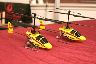
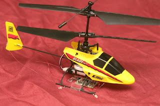
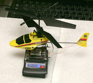
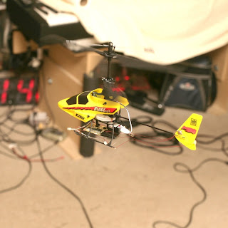
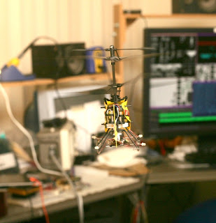
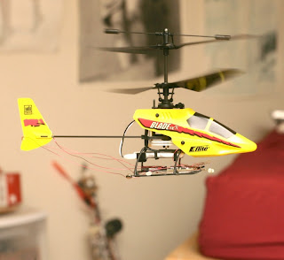
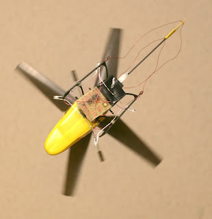
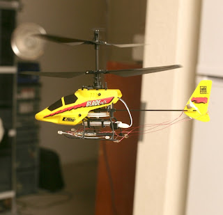
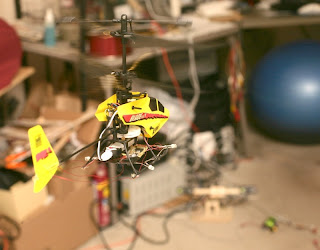
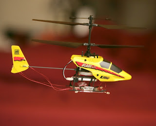
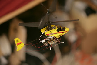
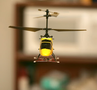
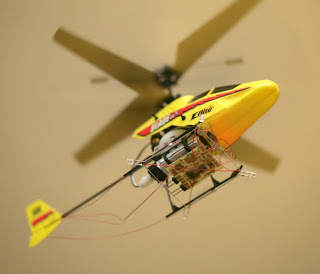
Automating the Blade MCX


The Blade MCX is a favorite of indoor micro UAV autopilot designers, even in the age of micro quad copters. The time had come to automate one.

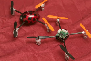
ladybird01.jpg


A test of a Ladybird showed the Blade MCX was much more stable.  It automatically damps its horizontal motion to a freakish level.  The ladybird flew for 5 minutes with a dummy payload.  It would have been an unknown amount less if the payload used as much power as the real autopilot.

The Blade MCX flew for 11 minutes without a payload.  Flight time was slightly longer without a canopy.

The full autopilot with IR leds & hot glue was 3.7 grams & reduced the Blade MCX to 2 minutes.  It would probably reduce the ladybird to an even more unacceptable time, but it would take some doing to test the current usage.


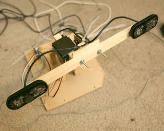
The largest problem was the 160mA required by the IR leds to give a light field the cameras would see.  This was the introduction of a pure IR camera system.

camera_mount05.jpg

stereo09.jpg

ir01.jpg


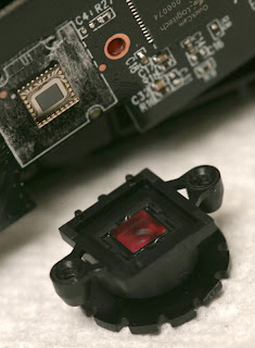
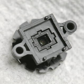
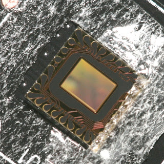
IR filter from edmondoptics.com was invaluable.  You need a filter which passes the IR band without attenuation to get a high enough frame rate.  Floppy disks & film rolls neither do that nor are they still produced.


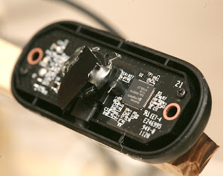
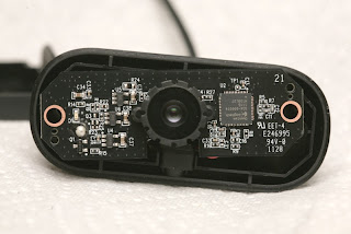
The camera of choice was the Logitec C210 webcam.  It was cheap, had manual exposure control, decent picture quality, & was easy to convert to IR. 

webcam02.jpg

webcam03.jpg

webcam04.jpg

webcam05.jpg


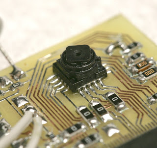
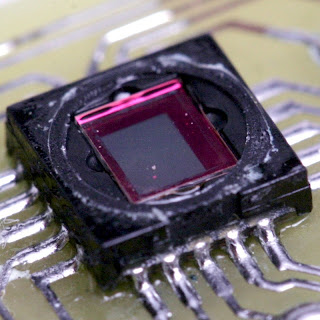
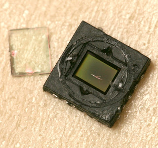
Unfortunately, the mighty TCM8230 from $parkfun couldn't be converted to an IR camera.

tcm8230_01.jpg

tcm8230_02.jpg

tcm8230_06.jpg


The IR filter is too close to the sensor to remove without damaging the sensor.

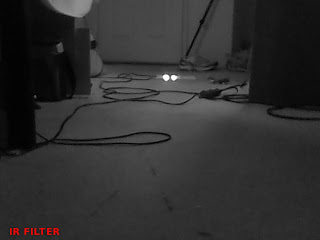
ir05.jpg


View from the Logitech in IR, with auto exposure.


blade16.jpg

blade17.jpg

blade14.jpg


Overriding the Blade MCX remote required just a 100nF, 1k, & 600khz PWM to generate a stick voltage.  The sticks were now overridden by software.  A 0-3.3V range was all that was required to control it, even though the stock remote did 0-3.5V.

It was very useful to have a 2nd controller to fly it manually, testing for whether a problem was in the autopilot or natural instability.

marcy3_11.jpg


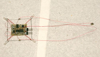
The Marcy 3 board has become the jellybean autopilot board for micro UAV's.  All it does is transmit the heading & provide 1.2V to the LED's.  In the future, it could be expanded to control the motors.

Indoor copters are such 1 hung low items, there hasn't been any incentive to replace their electronics. 


Solid IR leds have been superior to flashing, visible LEDs.  The IR spectrum has a lot more unused bandwidth.  They are still overpowered by lightbulbs & sunlight, but it won't be sunny here for another 7 months.  If only they didn't need so much power.

blade_mcx21.jpg


A fleet of Blade MCX's in various stages of testing.

blade_mcx15.jpg


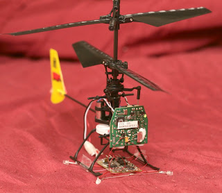
 The complete autopilot electronics.

blade_mcx18.jpg

blade_mcx16.jpg


 A final revision of the autopilot conversion.

blade_mcx17.jpg


 26.4g with autopilot.

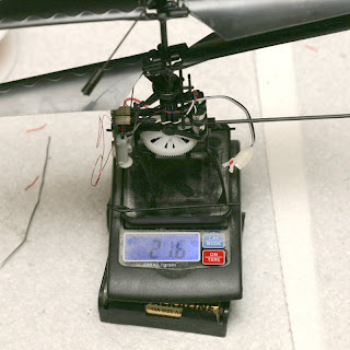
blade_mcx19.jpg


 21.6g with no canopy or autopilot.

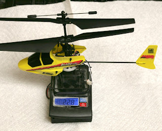
blade_mcx20.jpg


22.8g with canopy

blade_mcx08.jpg


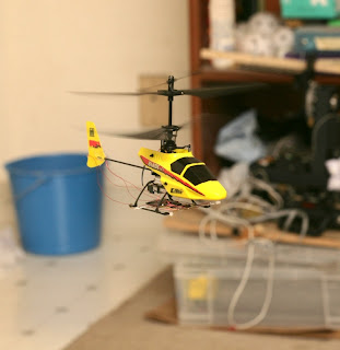
 It flies itself in the apartment.

blade_mcx09.jpg

blade_mcx10.jpg

blade_mcx11.jpg

blade_mcx12.jpg

blade_mcx13.jpg

blade_mcx14.jpg


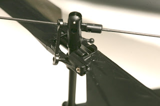
1 of the Blade MCX's developed a natural oscillation, early in its conversion.  There's no record of Blade MCX's developing a natural oscillation, on the goog.  The oscillation remaned, whether or not the autopilot was installed.  Nothing looked mechanically different or unbalanced, compared to a working Blade.  This is a mystery mechanical problem.


blade_mcx22.jpg


It turned out, the problem in internet lingo was "toilet bowl effect" & the solution was soaking the flybar assembly in 3 in 1 oil.  So now there are 2 autopilot capable Blade MCX's in the apartment.

It's a lot easier to photograph when it stays still.

blade_mcx23.jpg


blade_mcx24.jpg


blade_mcx25.jpg


blade_mcx26.jpg

Read more…

Lighter Yellow FPV Plane 869 Grams Air Frame

3689489661?profile=original

Yellow Plane 2 with inverted V tail software modified and tested stability gyros

Missing battery and camera box have a design which should weigh 140 grams empty.

The assembly shown below weighs 684 Grams no motor or electronics.

Electronics shown weigh 110 grams ESC Arduino board, Xbee, antenna & Gyro board

Motor & prop another 120 Grams


Yellow Plane 2 with inverted V tail Video 

RX Arduino code with mixing and closed loop stability
void UpdateServos()
{

//Digital inputs TX code helper
//TxVal[8] |= (digitalRead(5) << 0);//joy 2 push
//TxVal[8] |= (digitalRead(6) << 1);//pb
//TxVal[8] |= (digitalRead(7) << 2);//slide
//TxVal[8] |= (digitalRead(8) << 3);//toggle

//Throttle TxVal[1]
//Rotary pot TxVal[2]
//Joy 1 X TxVal[3]
//Joy 1 Y TxVal[4]
//Joy 2 X TxVal[5]
//Joy 2 Y TxVal[6]
//rssi TxVal[7]
//digital TxVal[8]
//micros() TxVal[9]

//Use the pot as the gain for all channels for now
float GainPot = (float)(TxVal[2]) * 0.001f;

//Get the target values from the TX
int PitchTarg = (TxVal[3] / 10);
int RollTarg = (TxVal[4] / 10);
int YawTarg = (TxVal[6] / 10);


//Prime the Target WOZ values
if(PitchTargWOZ == 9999)
PitchTargWOZ = PitchTarg;

if(RollTargWOZ == 9999)
RollTargWOZ = RollTarg;

if(YawTargWOZ == 9999)
YawTargWOZ = YawTarg;


//Get the Centered target values
float PitchTargCentred = (float)(PitchTarg - PitchTargWOZ);
float RollTargCentred = (float)(RollTarg - RollTargWOZ);
float YawTargCentred = (float)(YawTarg - YawTargWOZ);

//Calculate gains
float PitchGain = GainPot * 1.0f;
float RollGain = GainPot * 1.0f;
float YawGain = GainPot * 1.0f;

//Get Gyro values
float PitchGyro = (float)(AnIn[2] - AnInWOZ[2]);
float RollGyro = (float)(AnIn[1] - AnInWOZ[1]);
float YawGyro = (float)(AnIn[0] - AnInWOZ[0]);

//Calc P error
float PitchError = (float)PitchTargCentred + PitchGyro;
float RollError = (float)RollTargCentred + RollGyro;
float YawError = (float)YawTargCentred + YawGyro;

//Apply gains
int PitchTrim = (int)(PitchError * PitchGain);
int RollTrim = (int)(RollError * RollGain);
int YawTrim = (int)(YawError * YawGain);

//Constaring trim authority
PitchTrim = constrain(PitchTrim, -30, 30);
RollTrim = constrain(RollTrim, -30, 30);
YawTrim = constrain(YawTrim, -30, 30);

//Dump the trim value
if((TxVal[9] & 0x4) == 0)
{
PitchTrim = 0;
RollTrim = 0;
YawTrim = 0;
}


//Calc flap anglke
int Flaps = 0;

//Apply flaps
if((TxVal[9] & 0x8) == 0)
Flaps = -25;


//Throttle
val = TxVal[1] / 10;
val = map(val, 1, 179, 30, 179);
val = constrain(val, 1, 165); // scale it to use it with the servo (value between 0 and 180)
servo[0].write(val); // sets the servo position according to the scaled value


//Vee tail

//Left Elevator Joy 1 Y TxVal[4]
val = (YawTarg + YawTrim) + (PitchTargCentred + PitchTrim);
val = constrain(val, 15, 165);
val = map(val, 0, 179, 135, 45); // scale it to use it with the servo (value between 0 and 180)
servo[1].write(val); // sets the servo position according to the scaled value


//Right Elevator Joy 1 Y TxVal[4]
val = (YawTarg + YawTrim) - (PitchTargCentred + PitchTrim);
val = constrain(val, 15, 165);
val = map(val, 0, 179, 135, 45); // scale it to use it with the servo (value between 0 and 180)
servo[2].write(val); // sets the servo position according to the scaled value


//Left Flaperon
val = 90 + (RollTargCentred + Flaps) + RollTrim;
val = constrain(val, 15, 165);
val = map(val, 0, 179, 165, 15); // scale it to use it with the servo (value between 0 and 180)
servo[3].write(val); // sets the servo position according to the scaled value

//Right Flaperon
val = 90 + (RollTargCentred - Flaps) + RollTrim;
val = constrain(val, 15, 165);
val = map(val, 0, 179, 165, 15); // scale it to use it with the servo (value between 0 and 180)
servo[4].write(val); // sets the servo position according to the scaled value


//Joy 2 x nose Wheel
val = (TxVal[6] / 10);
val = map(val, 0, 179, 55, 125);
servo[5].write(val); // sets the servo position according to the scaled value

}


Read more…
3D Robotics

I was lucky enough to be part of GE's launch of their "Brilliant Machines" campaign, around the Industrial Internet and the intersection of ubiquitous sensors and big data. You can see the event here, including my own conversations with GE's Jeff Immelt and VC Marc Andreessen. But along with that came this inspired ad campaign. Don't miss the quadcopter at the end!

Read more…
3D Robotics

3689489436?profile=original

We had a a great time at the Drone Games at the Groupon offices in SF today. (They used to be called the Drone Olympics until they got a cease-and-desist from the Olympic Organizing Committee). Nine teams competed, all using Parrot AR.Drones running Node.js software. I was one of the judges

The winners were:

  • #1: James Halliday ("substack"), who wrote an insane virus that infects AR.Drones, which then infect other AR.Drones and causes them all to be p0wned and run amok. 
  • #2: A Stanford freshman team who wrote code that could allow one PC to simultaneously control many AR.Drones. (Not yet on Github but will be called "multidrone" when it is)
  • #3 "TooTall Nate", who wrote a cool way to control an AR.Drone over the cell networks with a Verizon MeFi card, for unlimited range. 

3689489484?profile=original

Co-Organizer Jyri Engestron and his partner, Caterina Fake, displaying the medals, which were created and 3D printed by Tinkercad (run by Kai Backman, the OTHER "Finn in San Francisco who used to work for Google")

3689489612?profile=original

The competition field 

3689489562?profile=originalThe judges! That's me announcing the winners (via Jyri Engestrom, one of the organizers)


Read more…

Fixing a 3DR frame weakness

3689489535?profile=original

One of the weak spots of the current 3DR frames is that the aluminum walls of the arms are very thin. The motors mount directly to the arm and in the event of a "landing anomaly" the aluminum wall is easily deformed by forces on the motor.

My solution was to construct "backing plates" for the motors. The plates fit inside the arms and slightly longer screws are used to attach the motors through the plates. The plates are simple 1/16" aluminum sheet drilled to match the 3DR mounting holes. The small indentation you see in between them in the picture below is for clearance of the motor axle, although it is probably not necessary as I don't think the axle protrudes further than the thickness of the arm wall.

This addition should improve the frame robustness somewhat, hopefully without merely identifying the next weakest link.

Read more…
3D Robotics

Raspberry Pi Quadcopter

3689489503?profile=original

Raspberry Pi is a superpowerful and popular new computer board, like Arduino but with a much faster processor and built-in video. It's not really designed for "physical computing" with lots of I/O like Arduino, and it's not open hardware so you can't make a version optimized for any particular task, so it's not a natural candidate for an autopilot. (It also runs Linux, which isn't a real-time operating system).  Nevertheless, Matthew Watson hacked together a PCB to work with the Raspberry Pi board and got a quadcopter to fly.

From Hackaday:

It was bound to happen sooner or later, but that doesn’t diminish the awesomeness of [Matthew]‘s Raspberry Pi-powered quadcopter.

[Matthew]‘s quadcopter is similar to all the other flying drones we’ve seen before with one important difference – all the processing, from reading the gyroscopes to computing exactly how much power to give each motor – is handled by a Raspberry Pi. This task is usually the domain of a microcontroller, as these calculations need to happen in real-time. The Linux distro [Matt] is running on his Pi has a lot more overhead than a simple AVR or ARM microcontroller, so doing everything that needs to be done in real-time isn’t guaranteed. With a bit of clever programming, [Matthew] managed to make sure all the necessary tasks were taken care of in time. It’s still not a real-time operating system, but for this project at least, it’s good enough.

Since the Raspberry Pi in [Matthew]‘s quadcopter is much more powerful than a microcontroller, there’s plenty of head room to SSH into the ‘copter while it’s flying. There may even be enough processing power to stream video to a web server; we honestly can’t wait to see what [Matthew] does with his flying Linux computer in the future.

You can check out [Matthew]‘s code over on the git or watch a few flight test videos over on his youtube.

Read more…

Arducopter build

3689489387?profile=originalI've been building a new Arducopter recently. Here are the ingredients:

  • RC Timer X650 frame (with Xaircraft cowl iso the supplied transparent dome)
  • RC Timer 30A ESCs with SimonK firmware
  • AX-2810Q 750KV motors with integrated prop adapters
  • GF1245 (12x4.5) props
  • APM2 with disabled GPS
  • LEA-6H GPS
  • XBee 2.4 (will be replaced with XRF module)
  • FrSky RC transmitter (8ch)
  • 3S 4000mAh battery

This setup is intended for hovering and endurance. Although I did not select the parts on color, I like the fact that it is all black ;-) A camera mount will be added to the setup after the initial test flights. Some things encountered during the build:

  • Weight: 1129gr (without battery), 1447gr (with battery)
  • Although space is available near the motor mounts for ESCs, this will only hold smaller ESCs. I decided to mount the ESCs under the cowl.
  • The arms can be folded in for transport. The legs are removable, but doing this often might weaken or break the plastic clamps I fear (see next point).
  • The curved landing gear legs are made of fairly stiff plastic, I will probably add some rubber bands or wire between the legs to prevent them from bending out too far.
  • The supplied transparent dome is nice, but the cowl from the Xaircraft original on which this frame is based looks way better in my opinion. It is lower and wider than the dome though.
  • Another advantage of the cowl over the dome is that the cowl locks the arms in place in both normal and folded configurations.
  • Compared to the Xaircraft original this kit misses one part: a relatively small rectangular piece of carbon intended as 'battery tray'.
  • The motors are low-kv, and are selected due to similar performance to other pancake-style motors. 

3689489348?profile=original

Read more…

Autonomous Waypoint Flight Mode in SmartAP!

Now SmartAP autopilot has Autonomous Waypoint Flight Mode. The demo shown in the video above consisted of 4 waypoints. After the last waypoint quadcopter came back to the initial home position and automatically switched to position hold mode there. Moreover, autopilot has Stabilize,Altitude Hold, Position Hold and Return to Home flight modes. Flight can be controlled and managed with QGroundControl Station.

You can find more information and other videos on my website: http://sky-drones.com/

Kirill

Read more…

Experimental Airframe - Goldschmied Pusher

3689489314?profile=original

Hi all,

I've only recently become part of the diy drones community and already I've learned a lot about amateur UA operations.

As my first contribution here I thought I'd share a design that I put together this morning based on some old research on laminar flow shapes.

It's a bit different. The fuselage here is a low drag shape developed by Fabio Goldschmied in the 60's, originally for airships. The principle involves a cusp at 82% along the body which the air over the fuselage is drawn through. This suction allows laminar flow to be maintained over up to 77% of the fuselage, reducing drag by 37% or more. Later Goldschmied proposed the use of this shape as an aircraft fuselage, in much the same configuration as I have here. The exhaust is spat out the back as shown below:

3689489405?profile=original

I decided to draw up a design for a hand-launched UA using this principle, with an EDF (small, around the size of the Zephy v70's) for propulsion. I have no idea how well this will work but at the very least the internal fan protect genius from the moving parts.

3689489364?profile=original

The specs for this are shown in the drawing above. I went for a mid-wing configuration to further reduce drag, but gave it some dihedral (3 deg) to maintain stability. This design should have good wing loading. The tail has been sized using volume ratios somewhere between that of gliders and homebuilts.

As an afterthought the housing for the fan is quite small, thus the fuselage may need to be scaled to accommodate an EDF with an outer diameter greater than 50mm.

Let me know what you all think!

- MB

PS. I have 8-10 weeks free over the summer and am looking for work experience, let me know if you are in the Melbourne area and have some work!

Read more…
3D Robotics

3689489294?profile=original

Vice did a really well-made 20-minute documentary on the domestic drone boom, including a fun visit to 3DR. Here's there description:

When Chris Barter, program manager for the Datron Scout micro unmanned aerial vehicle, isn’t surfing one of his favorite low-key spots near Oceanside, California, he’s selling his military-grade spy drone to standing militaries and law enforcement agencies across the world.

When Alan Sanchez and Sam Kelly, two young engineers with 3D Robotics, the open-source hobbyist drone company spun off of Chris Anderson’s non-profit community DIYDrones, aren’t tinkering in 3D’s charming drone-punk lab, they can be found at a neighboring field. Blissed out under the late afternoon sun, they pilot a pair of tricked-out RC aircraft—a small quadcopter and a more traditional glider plane, both outfitted with 3D’s custom autopilot—in lazy circles, mindful of small manned airplanes passing through the same airspace. Further off in the distance, a pack of Apache helicopters thumps past.

When Anderson, for his part, isn’t overseeing the entire operation with his business partner, Jordi Muñoz, shuttling back and forth between 3D’s research and development centers in San Diego and Tijuana, Mexico, he’s busy working his day job as editor of Wired. Wait—scratch that. Anderson just left Wired to focus on drones full time.

“It was one of those follow-your-heart things,” Anderson tells me over email. “The company is booming and we’d just raised a big VC round. I felt that this was my next big thing.”

He’s not alone in that thinking. These are just some of the key figures at the leading edge of American spy and hobby drones, of course. They represent only a thin slice of the southern California drone zone, a booming and buzzing tech sprawl borne of what historically has been a hotbed for aerospace R&D. But they’re a mixed, somewhat unpredictable, and dedicated lot, nonetheless—and as we saw first hand, just as mixed, somewhat unpredictable, and dedicated as the drones they know inside and out.

Without further ado, then, we present Drone On, Motherboard’s nosedive into this domestic drone boom. From military weapons expos in Jordan to idyllic SoCal beaches, we caught up with some of those who are building and selling unmanned aerial vehicles all over the world, and even convinced a few companies to let us take their flying spy robots for a spin.

It’s a story about not just the most overlooked facets of the American Drone Age – small-scale recon drones, not the ominously hulking and Hellfire-missile-toting hunter-killer drones so characteristic of American anti-terror missions abroad—as the Federal Aviation Administration ramps up the authorizing process for those itching to fly drones in US airspace. It’s a story about the fears, the uncertainties, and the hopes arising when tools once solely used in the military eventually seep over to law enforcement, various federal agencies, and everyday civilians, and quick.

Now, look up.

Read more…
3D Robotics

The DIY kid-tracking drone

3689489231?profile=original

Nice job by IEEE's Spectrum's Paul Wallich in creating a DIY "follow me" box (working with ArduCopter) to keep an eye on his kid on the way to school. Sample from the article, which appears in print this month:

On school-day mornings, I walk my grade-school-age son 400 meters down the hill to the bus stop. Last winter, I fantasized about sitting at my computer while a camera-equipped drone followed him overhead.


So this year, I set out to build one. For the basic airframe, I selected a quadcopter design for its maneuverability and ability to hover. Construction was straightforward: You can buy a quadcopter kit with all the pieces or, as I did, get parts separately and spend more time on system integration. 


On the mechanical side, there’s a central frame to hold the electronics, spars of aluminum to support the motors and propellers, and legs to cushion the quadcopter’s landing (I made a few extra sets of legs out of foam board for easy replacement). 


On the electronics side, there’s a main control board plus sensors, batteries, a power distribution board, power controllers for the motors (which draw tens of amperes, not what you’d manipulate with ordinary microcircuitry) and a radio receiver for standard remote-control flying, plus an RF modem for computerized control—I got both control systems for redundancy. 


For the main control board, I chose an ArduPilot Mega, mostly because it integrates everything I needed—the CPU, input/output ports, a three-axis gyroscope and accelerometer, and a barometric altitude sensor. A daughterboard soldered on top holds a thumbnail-size GPS unit, a magnetometer (compass), and a slot for microSD card storage. The whole board is powered by a 5-volt feed from one of the motor controllers. (When programming it on the ground, you can power the board via a USB connection.) 


(via SUASNews)

Read more…

CO2 Parachute System

I know that people have discussed this before, but I have yet to see anyone declare that they built a worthwhile system or create any documentation.  I did see some youtube videos using pyro charges, but that makes me nervous.  I want to use CO2.  If anyone has any information or observations I would love to hear it as I start this project.  I am throwing all my ideas out there to see what people would do differently, or to find out if it is a pipe dream (pun intended).  So here we go!

Goal:

Develop a lightweight and independent failsafe system for multicopters.

Idea Summary:

Use an Arduino micro with an accelerometer to trigger the ejection of a parachute.  The system will have to be independent of all other power and mechanical systems on board so it will have it's own power source.

Detail:  

This would be primarily designed for multicopters carrying a large and expensive payload like a DSLR.  The goal is to slow the copter down enough so that the payload is less likely to be damaged if an emergency occurs.  The independent power source must be small and light weight.

I researched different methods to see if anyone had tried to worked with Arduino and pressurized CO2.  Unfortunately, there were only unanswered questions or some hypothesis with no follow up.  While brainstorming I thought about paintball and thought that a solution might exist there since they use electric triggers in many of the markers.

I picked the CO2 system from the Tippman Tipx pistol because it was built around CO2 cartridges, instead of a refillable bottle system.  I think I can use the puncture valve assembly from this marker to interface with the CO2 cartridge.  I need to figure out if the puncture valve assembly will actually act as a valve, or if it only provides the breach.  I also need to find out if the an e-trigger solenoid provides enough force to puncture the cartridge, or if it has to be manually punctured.

The Solenoid will be triggered by an e-trigger assembly, this assembly will be hooked up to an arduino micro with an accelerometer.  The accelerometer will trigger the solenoid when either the multicopter tips past a certain point or the rate of descent reaches a specified velocity.

The gas from the CO2 cartridge will travel through a pipe into the adjacent tube that is packed with wadding and a parachute.  I will need to run some tests to see how big the chute needs to be, but I am sure it will be significant.

Reference:

Tipx Exploded Diagram: http://www.tippmann.com/pdfs/manuals/TiPX%20Schematic%208-11.pdf

Valve Puncture Assembly: https://www.pbsports.com/Tippmann-TiPX-Puncture-Valve-Complete.html

Solenoid & e-trigger: https://www.pbsports.com/Virtue-Redefined-Tippmann-A5-Upgrade-Board...

Arduino Micro: https://www.adafruit.com/products/1086

Accelerometer: https://www.adafruit.com/products/1018

Here is a really rough draft of what I am thinking:

3689489216?profile=original

So lets hear what you think!

Read more…
3D Robotics

3689489170?profile=originalOriginally designed for road/bike videos, it supports flight videos/tracks, too:

From the Google Earth blog:

GPS4Sport has just released a new product that combines GPS track data with action cam movies, then overlays the movie on top of the Google Earth plug-in while it all runs. It sounds complicated, and I'm sure it is on the back end, but the result for the end user is really quite cool.

You can watch a great example of one heregelogoicon.gif

It also supports flight activities, such as this one,gelogoicon.gif shown here:

flight.jpg

The flight mode supports video as well, though they don't have any examples of that yet. Check it all out for yourself at GPS4Sport.com.

Read more…